Step 1: How do I tune this thing?!?!
In parts 1 and 2 of this antenna saga I got my Cushcraft A4 repaired and all the individual parts tested, adjusted, and all the parts assembled into a antenna-shaped assembly of aluminum. No I’m faced with the question. How do I tune this thing when it is standing on sawhorses in my back yard?
A quick google search confirmed what I already knew, the resonance would move higher in frequency with increased elevation above the ground. So in theory I could tune the antenna on the sawhorses and then it would be right where I wanted it when installed on the tower. The trick is to predict how much the resonances will shift with elevation.
I searched through every resource I could find online about predicting the resonance shift and I received basically three answers; “Somewhat higher in frequency” and “It Depends” and the most frustrating answer of all “Raise the antenna to full height and measure the resonances. Lower the antenna and adjust in the right direction. Raise the antenna, re-measure, and repeat as necessary.”
I did find a useful article or two that suggested pointing the antenna straight up and elevating it 3-6′ above the ground. This made a lot of sense to me as a Yagi antenna is essentially designed to try to ignore whatever is behind it. Pointing it straight up was a promising answer to the tuning connundrum, but the more I thought about it the more I ran into roadblocks. Now it is important to note here the antenna is roughly 32′ wide from tip to tip and 18′ long from reflector to director. I can lift it from the center of the boom fairly easily, but it is much too unweildy and fragile for me to move it around too much.
The only thing I had nearby that was tall enough to lift the antenna was my tower itself, and I did not want to climb the tower just to install some kind of lift boom. Again, I just kept struggling with the details of HOW to do this actual BIG antenna stuff.
Surely there HAS to be a better way!
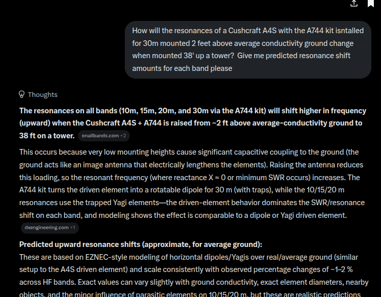
Well, they say necessity is the mother of invention. So I started looking for answers to the resonance shift prediction. The information I was able to find online was slightly useless. Most sites would say the resonances will “go higher in frequency” without any guess at the scale of the frequency shift. Some sites would say words like “significantly” or give vague answers such as “as much as a megahertz”. Surely there has to be a better way to predict how my antenna will act. Humans have over a century experience playing with these “radio wave” things, someone must have done the experiments at some time. The information I need must be out there somewhere. Then I had a tiny spark of an idea. “Let’s ask this new fangled AI thing for a prediction”
So I fired up x.com and asked GROK what it thought about my situation. It made some assumptions about my soil conductivity and did some “thinking” and spit out a reasonable sounding answer. We talked back and forth about the prediction a little bit and it all seemed like it just might work. This AI stuff is crazy!
Once our conversation was completed, I had Skynet’s best guess for the resonance shift for each band. (shown below)
Predicted upward resonance shifts (approximate, for average ground):
These are based on EZNEC-style modeling of horizontal dipoles/Yagis over real/average ground (similar setup to the A4S driven element) and scale consistently with observed percentage changes of ~1–2 % across HF bands. Exact values can vary slightly with ground conductivity, exact element diameters, nearby objects, and the minor influence of parasitic elements on 10/15/20 m, but these are realistic predictions for the height change from ~0.02–0.06 λ (at 2 ft) to ~0.4–1.1 λ (at 38 ft). onallbands.com +1
- 30 m band: ~ +100–200 kHz (roughly +1–2 %; strongest relative effect here because low height is only ~0.02 λ and final height is only ~0.39 λ).
- 20 m band: ~ +200–300 kHz (e.g., a modeled 20 m dipole shifts from ~13.975 MHz at 8 ft to ~14.200 MHz at 35 ft; your 2 ft start will be slightly more). onallbands.com
- 15 m band: ~ +250–400 kHz (scales with frequency; higher band means somewhat larger absolute shift).
- 10 m band: ~ +300–500 kHz (least relative effect because even at 2 ft it is already ~0.06 λ, but still noticeable).
So I whipped out my NanoVNA and started measuring each band.
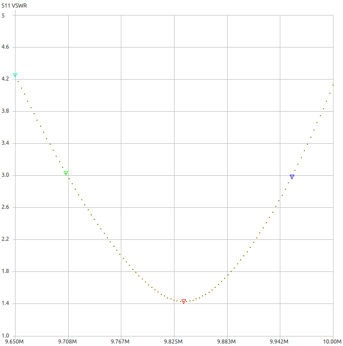
30 Meters was around 1.5:1 at 9.835Mhz and displaying a good looking curve. GROK predicts an upward shift of the resonance point of +100 to +200k. That shift would probably be OK wth me since 30m is such a narrow band. I can live with this.
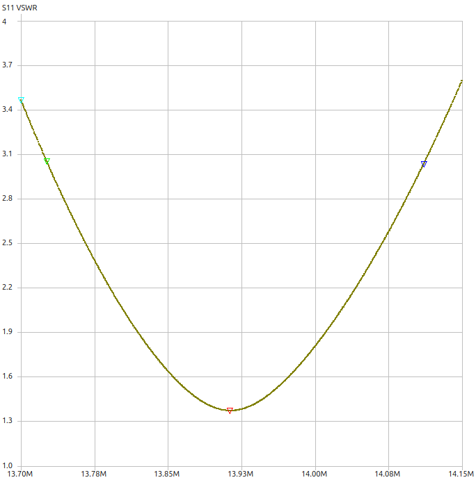
20 Meters showed a SWR of about 1.4:1 at 13.920Mhz and Grok says this will shift +200 to +300Khz. That should put my resonance close to 14.270. Yep! I can deal with that too.
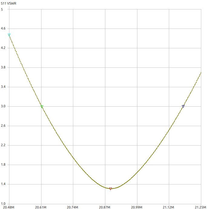
15 Meters was more of the same. Min SWR was 1.3:1 at 20.885Mhz. Grok expects +250 to +400Khz shift. That looks pretty good as well. If I get the full 400K shift then this will bullseye the center of the band. Send it!
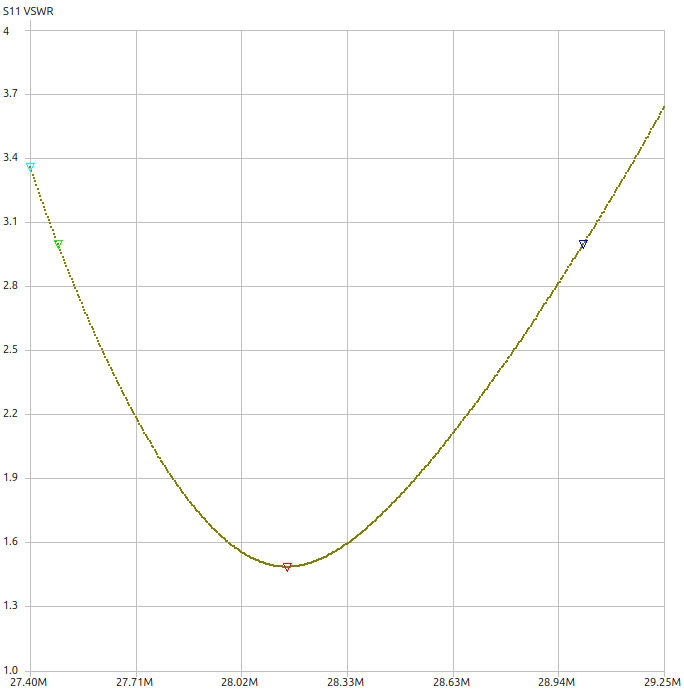
Finally 10 meters was showing 1.15:1 at 28.149Mhz with Grok expecting +300k to +500k of shift. This resonance looks quite a bit too low, but the bandwidth is really wide on 10m. Actually this band measured less than 3:1 all the way up to 29Mhz while on the sawhorses. I think it will be close enough for me.
I guess that’s close enough, time to raise this thing
So up the beanstalk I went! I had the trusty hands of my Father-in-law Joe and Don Kast KB7ZJP for help on the ground. First order of business was getting my trusty old MFJ 1836H Cobweb antenna down from the tower top and to get my ginpole mounted. I was planning to use the existing mast as the ginpole (a 12′ section of 1-1/4″ galvanized fence toprail). Well it turned out, the 1″ toprail was too small diameter to secure in my ginpole mount.
Plan B was a 6′ section of 1.5″ galvanized fence post that I just had lying around. This mounted right up and we had the ginpole in action! Next I removed the lower Yaesu thrust bearing and installed the new Yaesu G800DXA rotator in its place. Now it was time for masts!
The lift was uneventful, but as soon as the mast with the Sirio 50-3 reached the top it was clear. There was NO way I would be able to lift the mast up high enough to drop it into the upper thrust bearing. The 6′ fence post just couldn’t do it.
My pole was too short.
Story of my life
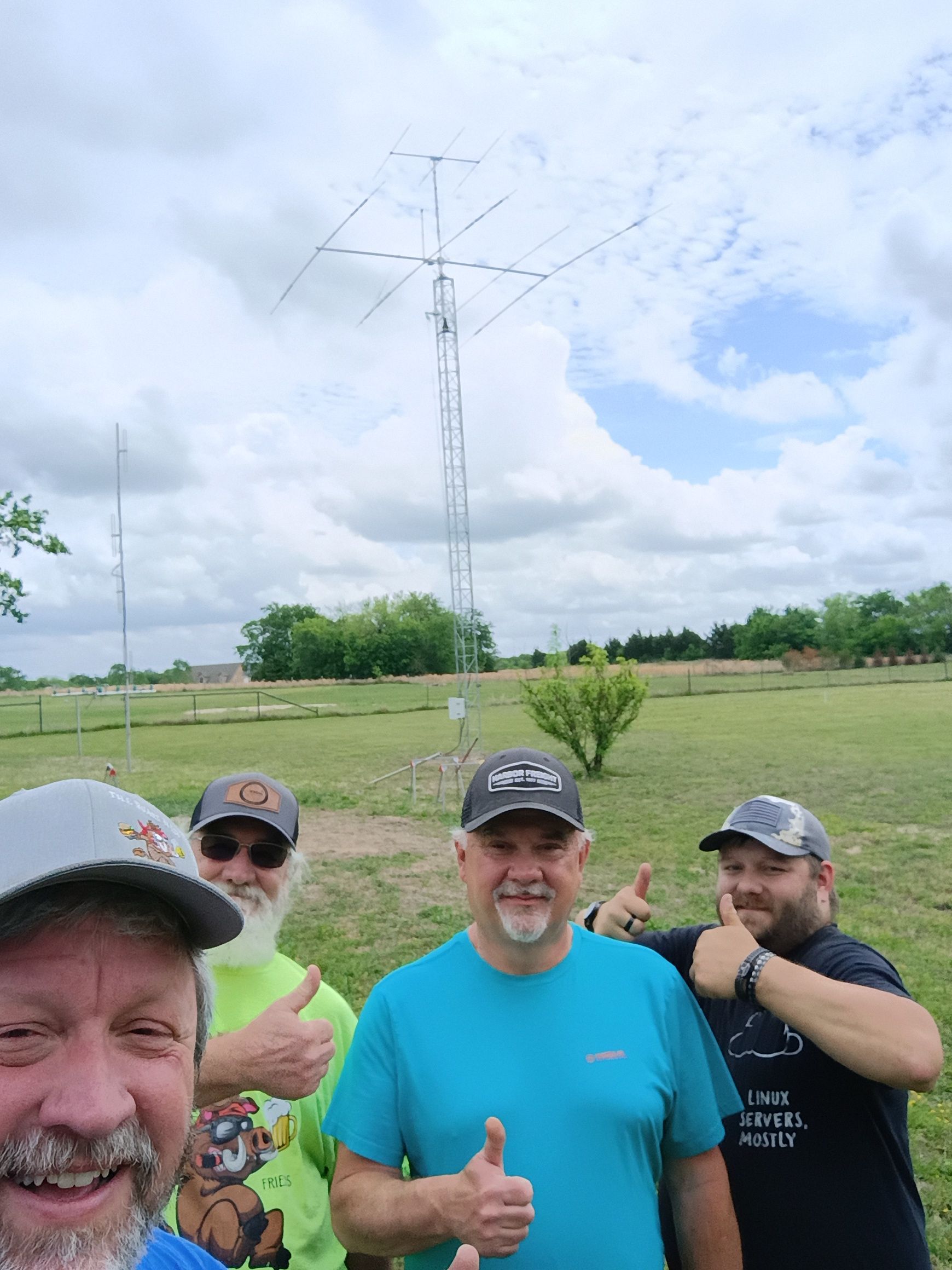
Two days later I was the proud owner of another 12′ section of 1.5″ Schedule 40 Aluminum pipe (cha-ching!). I had enlisted the help of a few more volunteers for the ground crew. Myself up the tower, Don again, Devlin (N5HB), Kevin (KI7MVY), and My friend from work Jonathon (KJ5HAQ).
Raising the mast and Syrio 50-3 6m Yagi went smoothly once we figured out the process. Then up came the big antenna.
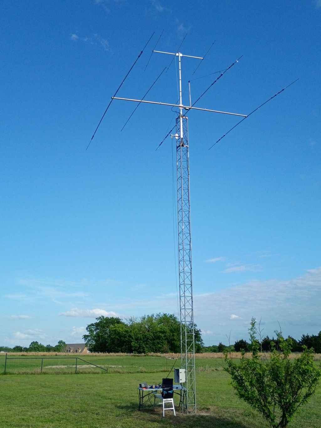
Honestly, it wasn’t nearly as hard as I expected it to be. At this point we had lifted a bunch of things up and down the tower and had the system pretty well figured out, but when the big lift happened it was just sort of routine. The guys rigged and lifted the antenna up to me. I manhandled it around to where it needed to be, and then I just bolted it in place. The biggest drama we had in the whole lift was one forgotten tagline tied to the end of the 6m yagi. With the help of a carwash brush on a pole I was able to drag the tagline over next to the mast and tie it off. It is still up there as a reminder to have a better plan next time I try to lift things 45′ in the air. But with all this said, we were done! The final lift took about 3 hours, and the whole process was maybe 5 hours of “Tower time”.
Nobody got hurt. Nothing got seriously bent or broken. Time for burgers and a little rest before starting the wiring.

SUCCESS!
So does it actually work? Tune in for the next installment of “As the rotator turns!”

Leave a comment